All powers SWR bridge and power meter 1st edition: may 2004 Revision 10d: august 2012 |
by Dominique - F1FRV
Aide technique (Français) Droits d'auteur (Copyrights)
For some countries, special informations, click on your national flag: ![]()
![]()
![]()
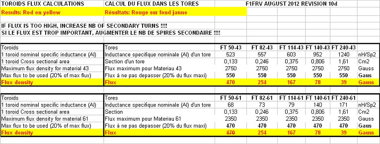
![]() EXCEL sheet with toroid true measured AL input.
EXCEL sheet with toroid true measured AL input.
![]() Peak power optional board.
Peak power optional board.
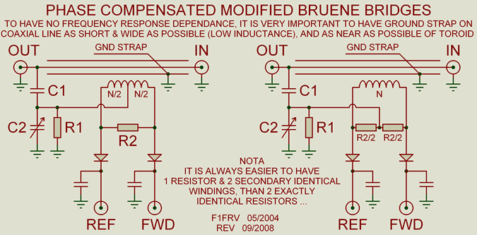
SWR AND POWER MODIFIED BRUENE BRIDGES
This design is applicable for small or high powers, from 100 kHz (or less) to 50 Mhz, from miliwatts to kilowatts, depending on the selected components. For best results, use the ferrite "43" material. Materials "4C6 or 4C65" generaly painted in purple, are identical to material "61" and can also be used (with much more turns than "43" for same inductance).
Material "2" iron powder (painted in red), are not in tables, as i strongly do not recommand their use. They can perhaps work for monoband designs, but definelitely not for wideband designs.
In theory, "61" or "4C6/4C65" could be used for 144 MHz, but i did not experimented by myselves...
Good suppliers for toroids are: PartsAndKits and AMIDON ...
PartsAndKits can also supply 1N5711, 2N7000, and trimmer capacitors .
With good electrical and mechanical design, using parts described here, and PCB designed for, 1.8 to 30 (50) MHz directivity can be better than 35 dB, and accuracy in power measurements in the range 1 to 2 %. Not so bad, isn't it ...
With different electrical or mechanical design, or misunderstanding of the excel sheet, please, do not complain if you obtain bad results, no or poor directivity, or transform resistor and wires into smoke and flammes.
Generaly, if it dont works, it is with people more clever, and better technicians than me, who dont want to follow EXACTLY what i wrote, and do what they feel instead.
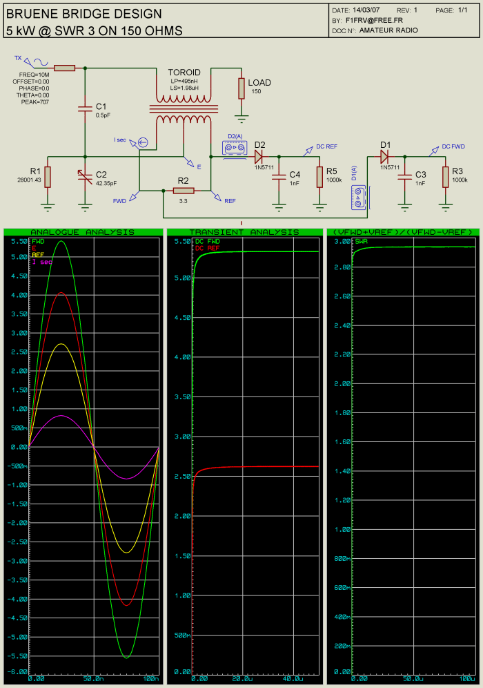
EXCEL sheet design example
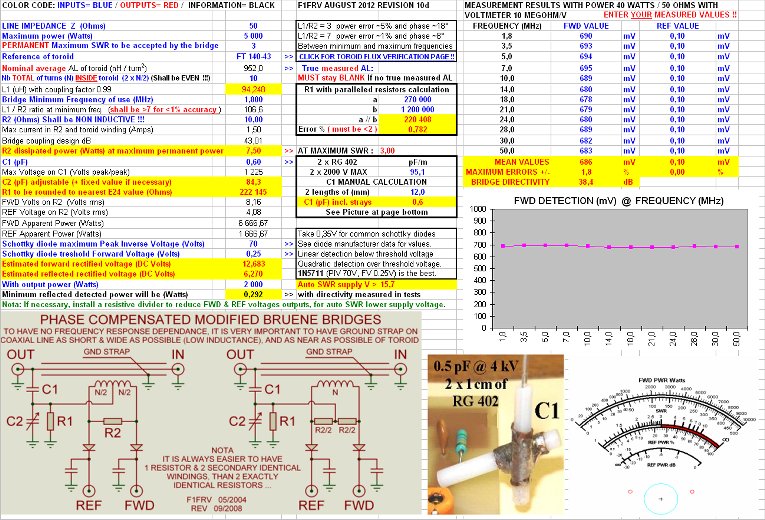
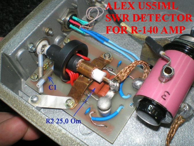
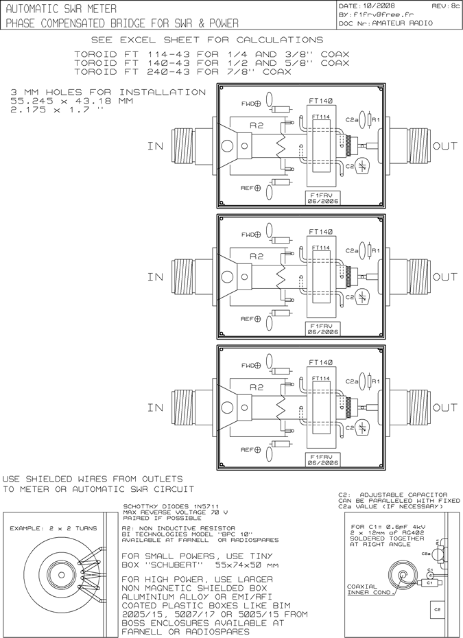
Nota: It is better to select the schematic with one resistor R2 and mid tap at coil, than the other scheme with 2 half values resistors. As it is easier to have EXACTLY the same nb ot turns in coil, than having EXACTLY the same values of the 2 resistors. Any difference in the 2 resistors values would give errors in SWR measurements results. Dont forget that turns number are the nb of turns counted INSIDE toroid hole .
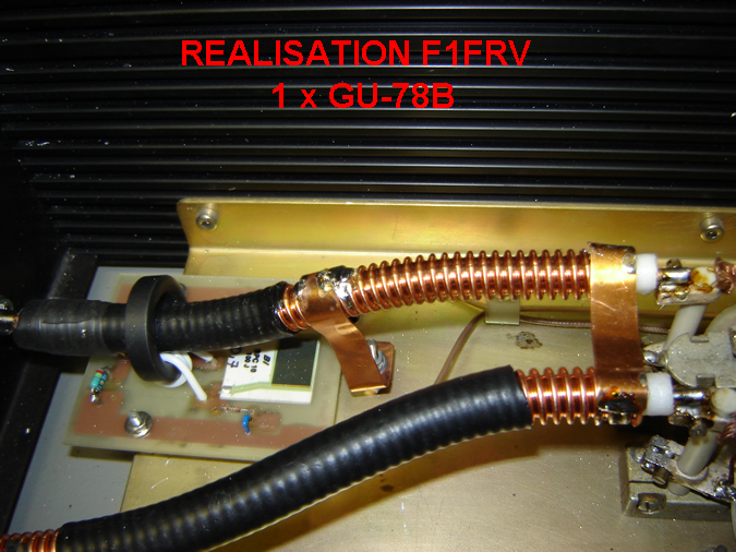
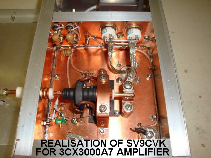
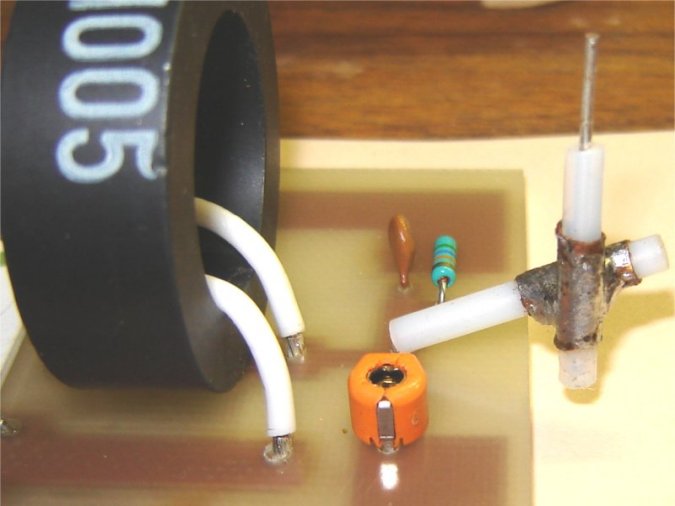
Place the WIDE ground return strip(s), not a single wire, between coaxial line, circuit board and main ground frame, as close as possible to the toroid, to have the best accuracy in POWER measurements over a wide range of frequencies. For SWR measurements ONLY, this is not very important, as the ratio FWD/REF is independant of absolute values of detected voltages.To avoid parasitic capacitances, place the PCB at least 5 or 10 mm above enclosure,
To have perfect balance of the bridge, with the calculated values given by EXCEL sheet, it is important to know the " TRUE " values of the coil(s), resistor R2, and capacitor C1. To know what is the exact Al value of your toroid, coil 5 turns of wire into it, measure with a LC meter, and divide value by 25.
The variable C2 capacitor, as shown, is MANDATORY, to compensate for all tolerances in components values, parasitics. During tests, dont hesitate to modify calculated value of C2 (fixed + adjustable value) to obtain the best balance.Tolerances and parasitics management is unfortunately not an exact science.
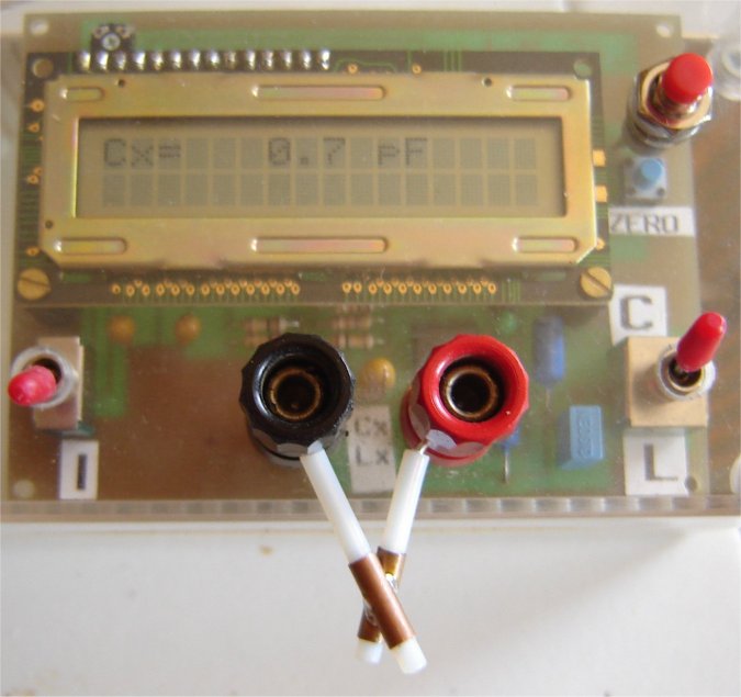
Check of coil(s) and capacitor C1 exact values can be made with a LC meter, like the one described in pages " Technical " and proposed by DF1SR (ex DD0SB).
Adapt cross sectional area of wires in toroid to maximum current in R2, do not undersize, 3 Amps by square milimeter is a maximum.
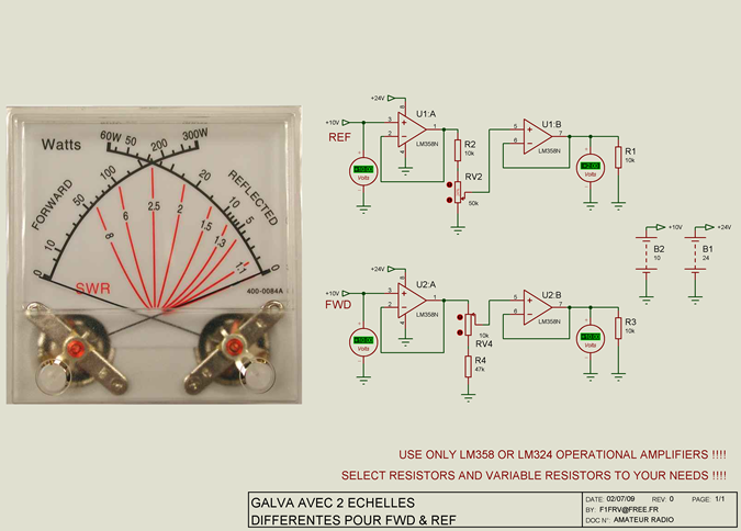
Load on detector diodes is a first order parametre for rectified voltages output. Do not hesitate to use operational amplifiers LM358 or LM324 as buffers (they include GND in common mode range). In this case, with very high impedance detectors load, to avoid too high time constant in SWR readings, reduce, if necessary, the values of decoupling capacitors in FWD & REF outputs (10 nF is OK with operational amplifiers, 100 nF or more without operational amplifiers).
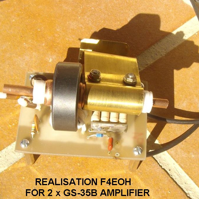
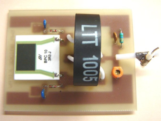
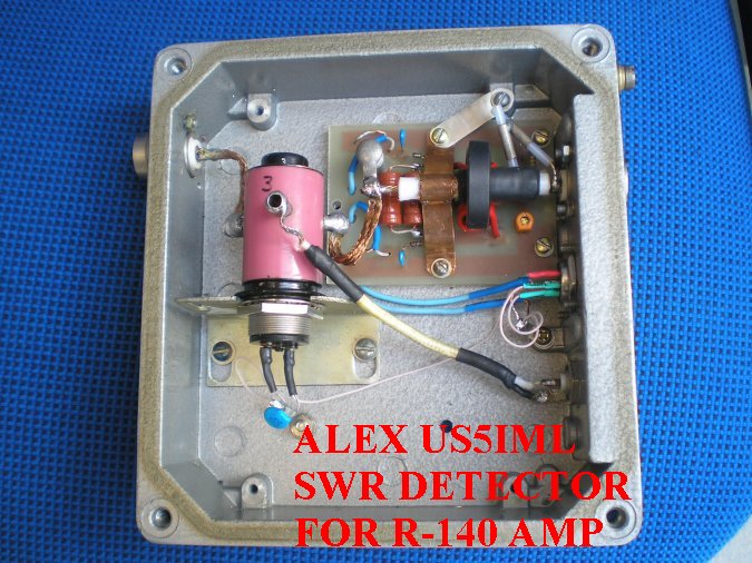
Note the wide ground strap (12 x 0.5 mm) behind toroid
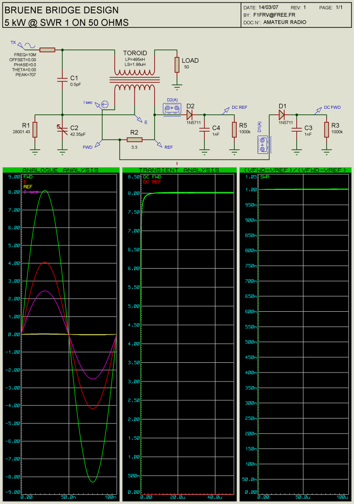
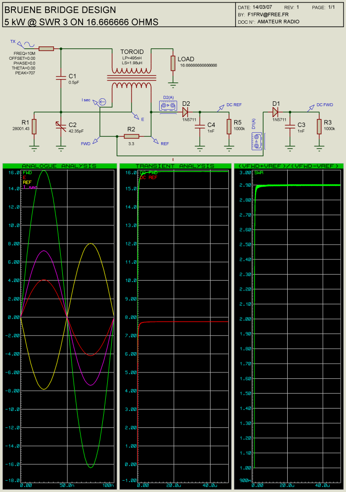
Simulations of the bridge phase & balance
Bridge old revision 3 PCB & components picture
Detail of the 0.5 pF @ 4000 V capacitor ( 2 x 10 mm of copper of RG402 )
Measurement of a 0.7 pF @ 4000 V capacitor ( 2 x 14 mm of copper of RG402 )
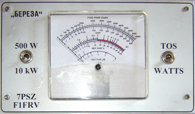
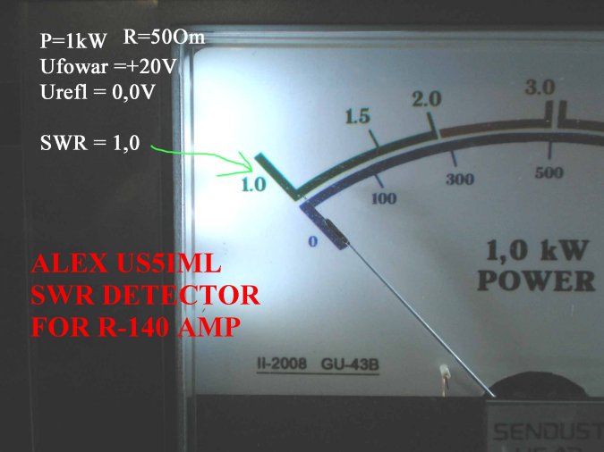
Front plate with meter
Meter scales can be made with F5BU’s POSTCARDWARE “GALVA” available HERE.
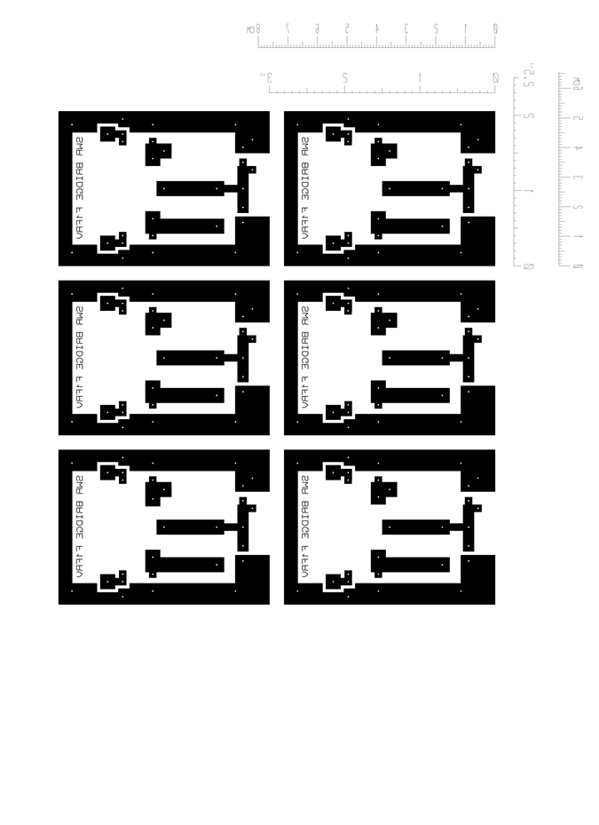
Download EXCEL sheet, components datasheets, example files for GALVA (SWR and power meters scales), and files for PCB:
Internal link to SIMPLE PEAK WATTMETER BOARD
Internal link to Automatic SWR meter
Internal link to DD0SB low cost LC meter
Enjoy
That’s All Fox ! ! ! !
Dominique - f1frv@sfr.fr
OR